
Key Technologies for Core Elements of Liquid Cooled Load Bank Design: Flow Control, Temperature Difference Optimization, and System Stability
Time:2025-08-18
In high-density computing scenarios (such as AI servers and supercomputing centers), Liquid Cooled Load Banks have become a core solution to break through heat dissipation bottlenecks. Compared with traditional air cooling, liquid cooling technology supports the stable operation of kilowatt-level chips with higher heat dissipation efficiency and lower energy loss. However, the design of liquid-cooled load banks is not simply a "liquid replacement for air"; their performance depends on the collaborative design of three core elements: flow control, temperature difference optimization, and system stability. This article will deeply analyze the technical logic and implementation paths of these three elements.
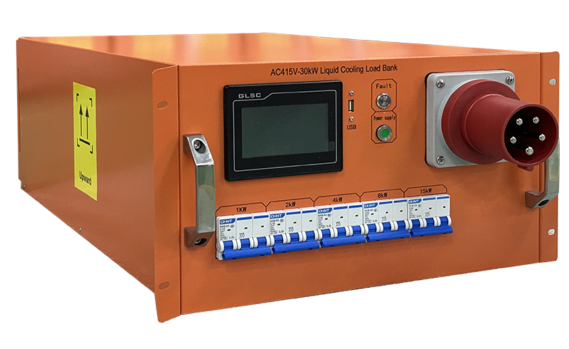
30kW Liquid Cooled Load Bank
30kW Liquid Cooled Load Bank
I. Flow Control: The "Power Hub" of Liquid Cooling Systems
Flow control is the foundation of liquid-cooled load bank design, directly determining heat dissipation efficiency and energy balance. Its core goal is to accurately regulate the coolant flow to meet the heat dissipation needs of heat sources, avoiding energy waste caused by "over-cooling" or equipment overheating due to "under-cooling".
(1) Accurate Calculation of Flow Demand
Flow design must be based on heat source power. According to the heat conduction formula, there is a clear relationship between coolant flow (Q), heat source power (P), coolant specific heat capacity (C), and inlet-outlet temperature difference (ΔT): Q = P/(C×ΔT). For example, when the GPU power consumption of an AI server reaches 500W, using a water-based coolant with a specific heat capacity of 4.2 kJ/(kg·℃), if the inlet-outlet temperature difference is set to 10℃, the required flow rate must be at least 0.012 L/s (approximately 43 L/h). In actual design, flow attenuation caused by pipeline friction and local resistance must also be considered, usually with a redundancy of 10%-15% reserved.
(2) Dynamic Flow Regulation Technology
Fixed flow design struggles to adapt to load fluctuation scenarios (such as computing power changes during AI model training). Dynamic flow regulation technology achieves intelligent adaptation through the following methods:
Variable Frequency Pump Control: Using variable frequency centrifugal pumps, which automatically adjust pump speed to change flow by real-time monitoring of chip temperature or inlet-outlet temperature difference. When the load decreases, pump speed drops, reducing energy consumption by over 30%.
Zoned Flow Control: In multi-heat source systems, independent adjustment of branch valves allocates larger flow to high-power components (e.g., GPUs) and smaller flow to low-power components (e.g., memory), achieving "on-demand cooling".
Flow Monitoring Feedback: Deploying electromagnetic or ultrasonic flowmeters at key nodes to collect real-time flow data and feed it back to the control system, forming a "monitoring-regulation-closed loop" dynamic response mechanism.
II. Temperature Difference Optimization: The "Key Lever" Balancing Efficiency and Energy Consumption
Temperature difference, referring to the temperature difference between coolant inlet and outlet (ΔT), is a core parameter in liquid-cooled load bank design. Its design must find an optimal balance between heat dissipation efficiency, equipment safety, and system energy consumption.
(1) Scientific Definition of Temperature Difference Range
Excessively small temperature differences (e.g., <5℃) reduce the heat carried by coolant per unit volume, requiring larger flow rates to meet cooling needs and directly increasing pump energy consumption. Excessively large temperature differences (e.g., >20℃) may cause overheating at the heat source outlet, exceeding chip tolerance thresholds (typically CPU/GPU maximum junction temperature ≤95℃), while exacerbating thermal stress in pipelines and reducing system lifespan. In practice, temperature differences in cold plate liquid cooling systems are usually controlled at 8-12℃, while immersion liquid cooling systems, with higher efficiency, allow wider ranges of 12-15℃.
(2) Technical Paths for Temperature Difference Optimization
Heat Exchanger Matching Design: Heat exchangers are core components for coolant cooling, whose area and fin structure must match temperature difference requirements. For example, in high-temperature difference scenarios, microchannel heat exchangers increase heat transfer area to improve efficiency; in low-temperature difference scenarios, compact heat exchangers reduce resistance loss.
Coolant Selection Adaptation: Different coolants have varying thermal conductivity and specific heat capacity, significantly affecting temperature differences. Water-based coolants, with high specific heat capacity, suit low-temperature difference, large-flow scenarios; mineral oil coolants, with good insulation but lower specific heat capacity, are more suitable for high-temperature difference, small-flow immersion systems.
Dynamic Temperature Difference Adjustment: By linking flow control with cooling fans (in air-cooled heat exchanger scenarios), temperature differences are dynamically adjusted during load fluctuations. For example, during load surges, flow rate and fan speed increase simultaneously to maintain stable temperature differences; during load drops, fan speed decreases, allowing slight temperature difference increases to reduce energy consumption.
III. System Stability: The "Fundamental Guarantee" for Reliable Operation
The stability of liquid cooling systems directly relates to equipment safety and maintenance costs, requiring design coverage of three dimensions: leakage prevention, anti-interference, and long lifespan.
(1) Leakage Prevention and Sealing Technology
Liquid leakage is the greatest risk in liquid cooling systems, potentially causing equipment short circuits and corrosion. Core protection technologies include:
Multi-Level Sealing Design: Adopting "O-ring + thread compression" dual sealing at pipeline interfaces and cold plate-chip contact areas, with additional sealant reinforcement at key nodes; static sealing pressure must be ≥0.6MPa.
Flexible Pipeline Adaptation: Using high-pressure resistant, anti-aging silicone or fluororubber hoses to reduce pipeline fatigue damage from vibration (e.g., server fan operation); pipeline bends use arc transitions to avoid stress concentration from right-angle bends.
Leakage Monitoring and Early Warning: Deploying humidity sensors or conductive probes in leakage-prone areas; upon detecting leakage, immediately triggering sound-light alarms, cutting off pump power, and activating backup cooling solutions (e.g., emergency air cooling).
(2) Material Compatibility and Anti-Corrosion Design
Incompatibility between coolants and system materials can cause corrosion and scaling, seriously affecting stability. Key considerations include:
Material Selection Matching: Metal components (e.g., cold plates, pipelines) prioritize corrosion-resistant aluminum alloys (6061-T6) or stainless steel (304); anode oxidation or passivation treatment is required for contact with water-based coolants. Non-metal components (e.g., seals) must resist chemical erosion from coolants (e.g., ethylene glycol in long-life antifreeze).
Coolant Maintenance: Regularly monitor coolant pH (maintained at 7-9) and conductivity (≤10μS/cm); add corrosion inhibitors (e.g., benzotriazole) to prevent metal corrosion and avoid system blockages from water quality deterioration.
(3) Redundancy and Fault-Tolerance Design
To address single-point failures, high-reliability liquid cooling systems require redundancy:
Dual Pump Redundancy: Main and backup pumps are parallel-designed; when the main pump fails, the backup pump starts automatically within 0.5 seconds, with flow interruption time <1 second.
Pipeline Redundancy: Critical paths use "main-standby" dual-pipeline design; in case of main pipeline failure, switching to the standby pipeline ensures uninterrupted coolant circulation.
Intelligent Early Warning System: Deploy pressure, temperature, and vibration sensors to real-time monitor system pressure fluctuations, component temperature rises, and pump vibration. Combined with AI algorithms, it predicts potential failures (e.g., pump bearing wear) and triggers maintenance alerts in advance.
Conclusion
The design of liquid-cooled load banks integrates flow control, temperature difference optimization, and system stability. Flow control provides "precision power" for cooling, temperature difference optimization achieves "energy efficiency balance", and system stability 筑牢 s the "safety bottom line". As computing density continues to rise, collaborative innovation in these three elements will drive liquid cooling technology toward higher efficiency (heat dissipation power density>500W/cm²), lower energy consumption (pump power ratio <5%), and longer lifespan (mean time between failures >100,000 hours), providing more reliable cooling support for core scenarios such as AI and supercomputing.
News Recommendation
-
 2026-05-28
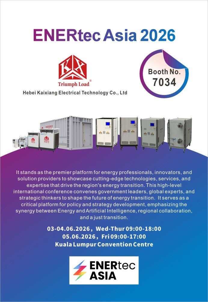
TRIUMPH LOAD EXHIBITING AT ENERTEC ASIA 2026
-
 2024-09-11
TRIUMPH LOAD EXHIBITING AT Enlit Europe 2024 -BOOTH 7.H08
-
 2023-04-21
TRIUMPH LOAD EXHIBITING AT DATA CENTER WORLD GERMANY 2023-BOOTH F909
-
 2023-04-06
TRIUMPH LOAD EXHIBITING AT ELECTRIC POWER TECH KOREA 2023 – Booth G109
-
 2022-05-05
What is the role of ac load bank for power supply?
